Assembling Motor Control
In the spirit of our middle-out approach, we can assemble functional actuator control logic by embedding conventional processors on individual building blocks.
With a small processor, like the ATtiny10, and an h-bridge, like the DRV8838, we can drive current through the actuator coils bidirectionally in a controlled way.
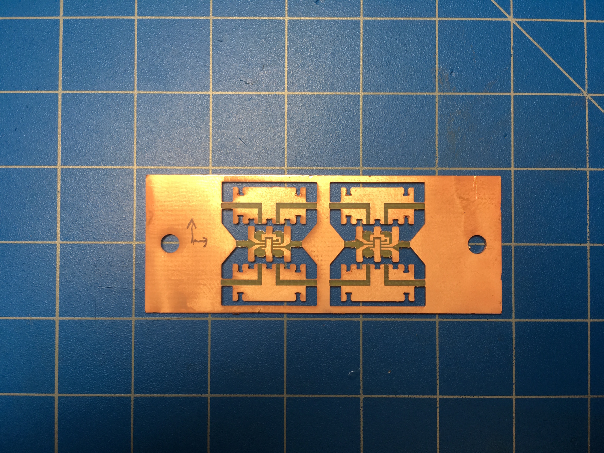
Both parts are fabricated in the same way that the flip-flop parts are made: machined from copper clad FR4 on the Roland MDX-540. The ATtiny part has four signals connected and so has room for nice pressfit connectors. The H-bridge part on the other hand, needs to house six signals and so makes-do with a much simpler castellated design to convey the signals into the struts.
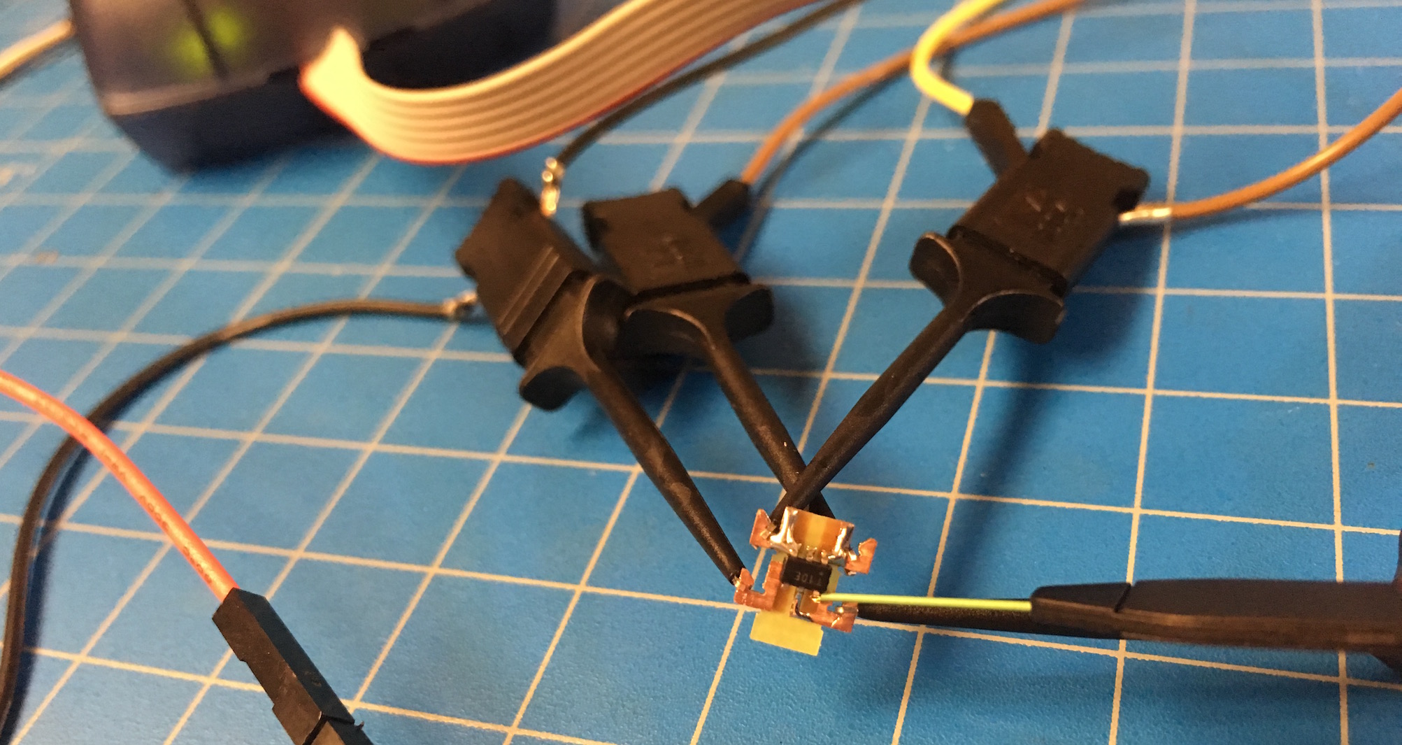
Once the parts are milled, stuffed, and assembled, the ATtiny needs to be programmed to generate the required phase and enable signals for the H-bridge. I originally intended to implement the PWM using the timer/compare module but found it took over control of the other GPIO pins. Instead, I ended up bit-banging the PWM. This actually works quite well, even at 10kHz, and enables a lot of flexibility in re-assigning pins. In this case, I programmed the ATtiny to output a triangle wave, toggling the GPIO direction pin every period.
Ultimately the parts are assembled and integrated with the actuator, mechanism, and structure. The device below shows an actuated mechanism with all of the control logic on-board. Power is the only thing provided externally.