Circuits
With three part types:

We can assemble various routing cells:

And then, through the arrangement of those cells, we can route traces in 2D:
With the addition of split-conductivity struts,
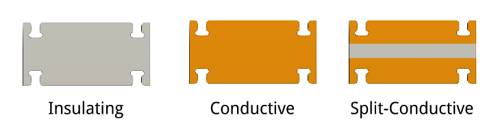
we can isolate traces on the upper and lower portion of nodes and allow crossover within the same node/cell:

An additional crossover part is necessary to be able to route the bottom of one node to the top of a neighbor node (and vice versa):

Fabrication
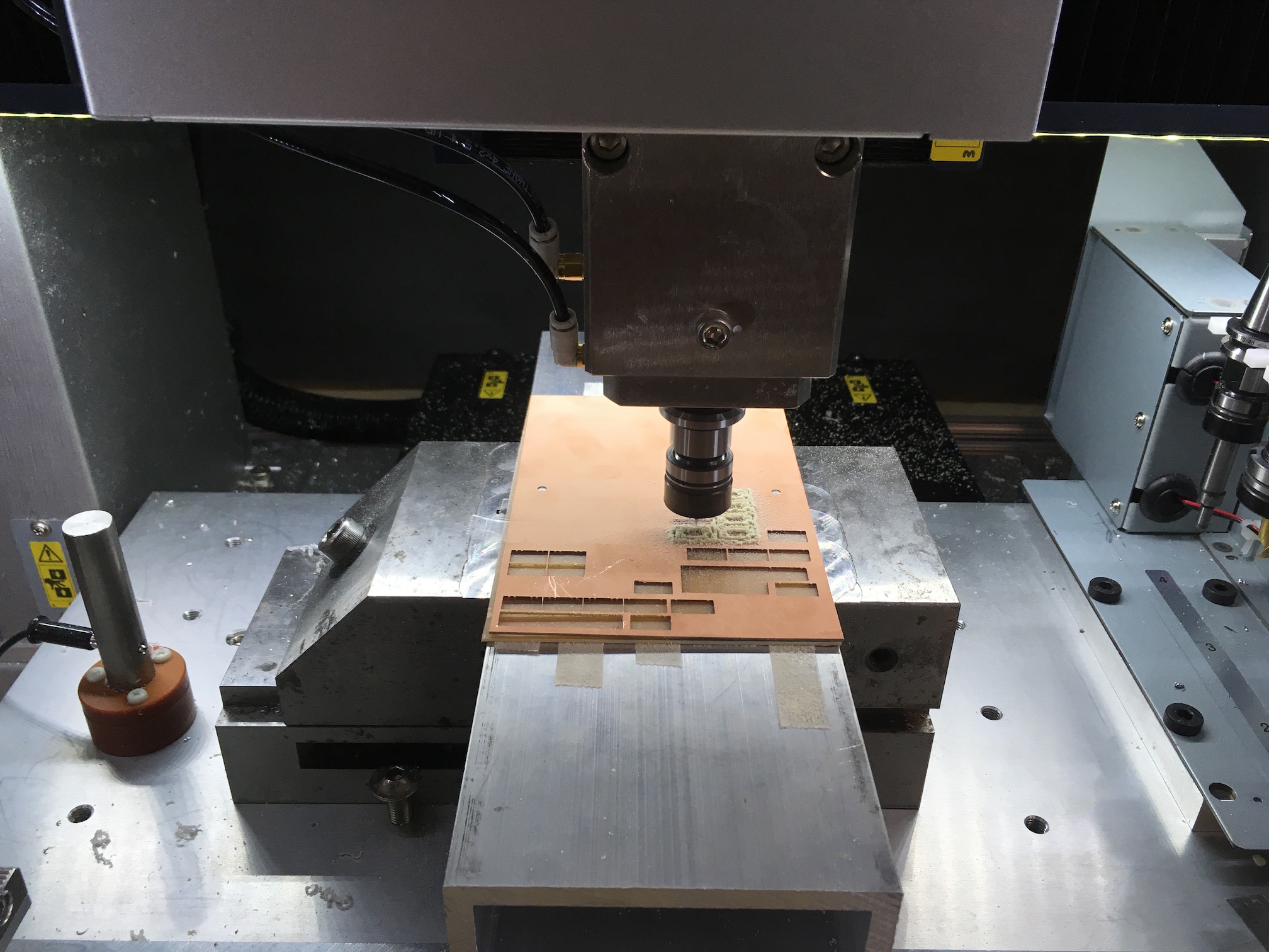
These parts can be fabricated fairly easily by milling them from copper clad board. I'm using 1/32" thick copper clad FR1 board with 1 oz (1.4 mil) double-sided copper. The Roland MDX-540 is a great tool for this job because the automatic tool-changer enables the use of rough and finish tools to deal with rapid tool wear. To do double sided milling, I drill two registration holes through my board and the fixture plate. I can then use 1/8" taper pins to position the board with high precision after flipping it over.

Testing
I first tested the continuity of the conductive joints by constructing a simple LED assembly. Here, ground is supplied by the bottom half of the node and power is supplied by the top half. Many LED's could be wired in parallel using this routing scheme.

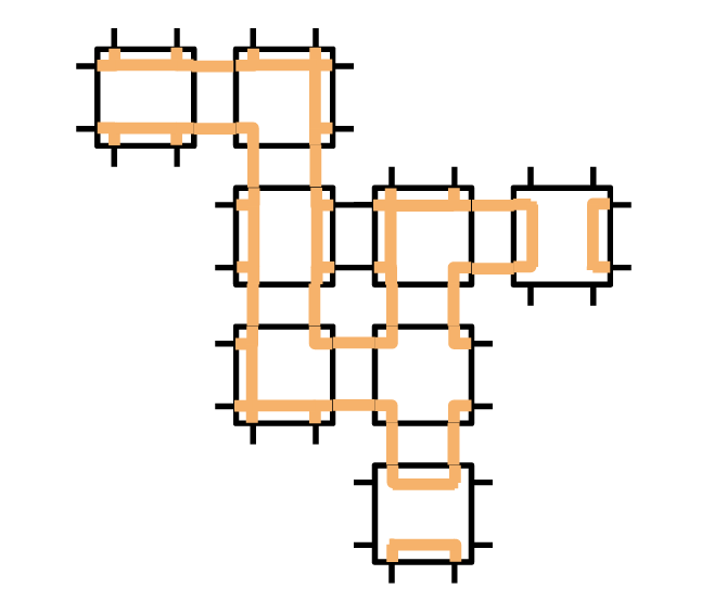
A more complex routing example is needed to route traces for Neopixel parts. Each neopixel has four connections: power, ground, data in, and data out. The power and ground should be wired in parallel while the data in and data out allows you to chain the neopixels serially.
To route this example, the split-conductive node and split-conductive strut are needed. Additionally, a crossover strut is required in order to have a signal change layers in the structure. Here, signal wires to control three neopixels independently are routed through the structure:
![]()
Power, ground, and a signal data input signal are supplied externally at one node of the structure and the signals are routed based on the construction of the structure.
![]()
![]()